
LC3-SeBRA
Low Cost Camera Controlled Self-Balancing Robot Arm
This is a personal project, where I wanted to integrate most of the important concepts of robotics, and at the same time, not spending much money. In simple words, this is a self-balancing robot (SBR) with a robot arm (RA) attached to it, so when the RA is contracted, it behaves like a normal SBR, but when the RA is extended at some point, the mass distribution changes, so now the center of mass is not in the chassis vertical axis (like when it was a simple SBR) and the vertical position is not stable anymore, then the system has to obtain the new stable (balance) position and mantain the SBR around that stable position. The utility of the RA is that it can pick up small objects whose relative position is obtained from real time image processing with a webcam on the ceiling.
As this is a complex project for me, I’ll split it into functional stages, where each new stage contains the previous one. Here I’ll list the stages and the concepts related to each one:
- Stage 1: Design and construction. (actuators, needed torque, dimension compatibility, CAD drawing, 3D modeling, laser cutter).
- Stage 2: Self-balancing robot. (PID)
- Stage 3: SeBRA. (inverse and forward kinematics, torque control)
- Stage 4: CC-SeBRA. (OpenCV)
Stage 1: Design and construction
Since it is a low cost project, I had to think about construction methods available for me and components I had already. 3D printing wasn’t an option beause I didn’t have neither the printer nor the filament, so a good option was to use my university’s laser cutter and just buy a MDF board (cheaper than acrylic sheet). The robot actuators had to be the cheapest ones that meet the requirements (maximum torque needed).
Components needed for the LC3-SeBRA:
- 2 DC gearmotors for the SBR
- 3 servos for the RA
- microcontroller
- motor driver
- accelerometer/gyroscope
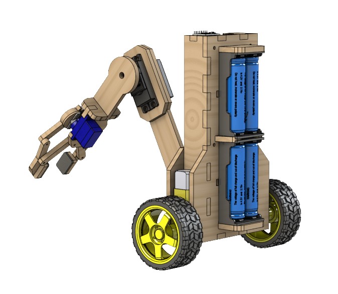
- batteries
- voltage booster
- charger module
The batteries used were the 18650 Lipo ones, since I have a bunch from laptop batteries. The cheaper charger module for these batteries is the TP4056 and a high current voltage booster is the XL6009. The microcontroller used was the ESP32 since I already had one and it is more powerful than Arduino Nano. The accelerometer is the basic one, MPU6050 (with gyroscope). The cheapest hobby DC gearmotors I found were the classic plastic gearmotors and the driver for them is the L298N (here it’s not needed to have high torque motors, since they will move around a stable position). To choose the right servo motors I did have to do some calculations (\(\tau_{max-needed} = \tau_{extended-arm} + I\alpha\)).
So after calculations, the right servos seemed to be 2 MG996r for the arm joints and a SG90 for the gripper. I also had to calculate the total current needed for all components to know how much batteries I needed to have around 2 hours of autonomy (and also to choose the right voltage booster). The right number seemed to be 4 (7200mAh).
After knowing the components I was going to use, I started to draw the robot taking in consideration the dimension and location of each component and the range of motion of the RA. Another consideration is that the asembly mode of the chassis was going to be through sockets (laser cutter compatibility).
General design:
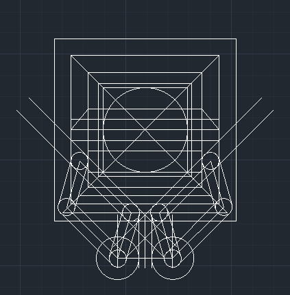
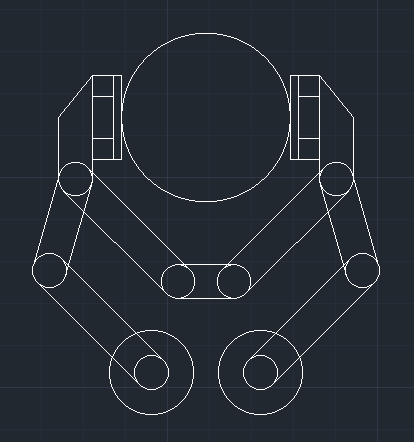
The easiest way I found to design the chassis was to draw in 2D all the component dimensions (as boxes) and then start seeing the final position each component should have. Also, the design of the gripper was quite challenging, because its geometry is based on parallelograms and gears, so the first thing I did was to draw each “finger” with its parallel couple and then I had to search for a gear shape that fits inside the gripper base. After all this, I had these results (the gripper was designed to pick up a ping-pong ball):
First design of the gripper:
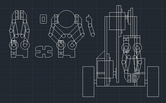
Final distribution design:
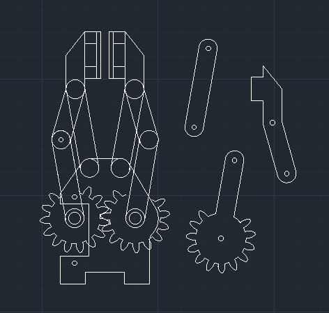
After realising how the gears should fit inside the gripper base:
The next step was to start drawing the MDF chassis parts that assembly to each other:
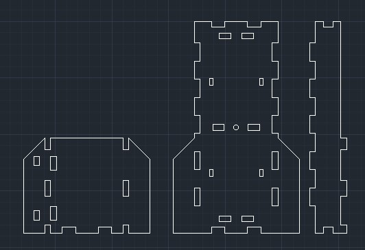
Then it was time to seach for each component 3D model, start creating the MDF parts and then assembly them all.
Images of the finished gripper:
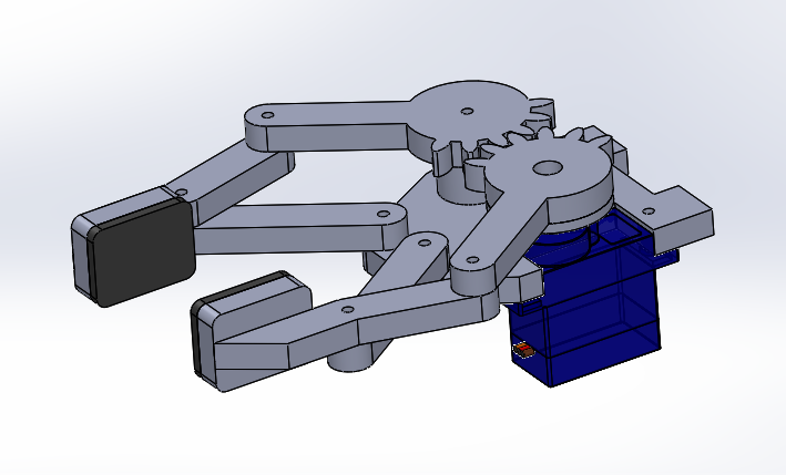
It can be seen that the gripper has natural stoppers.
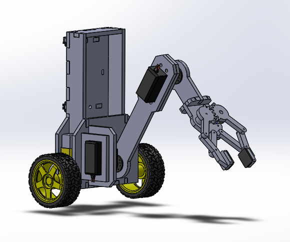
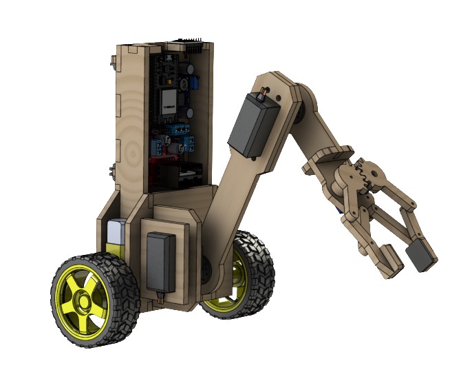
Images of the almost finished robot:
The only step left to do was to make all electronics fit inside the robot compartment. So first I had to know how they are connected, here it’s the scheme:
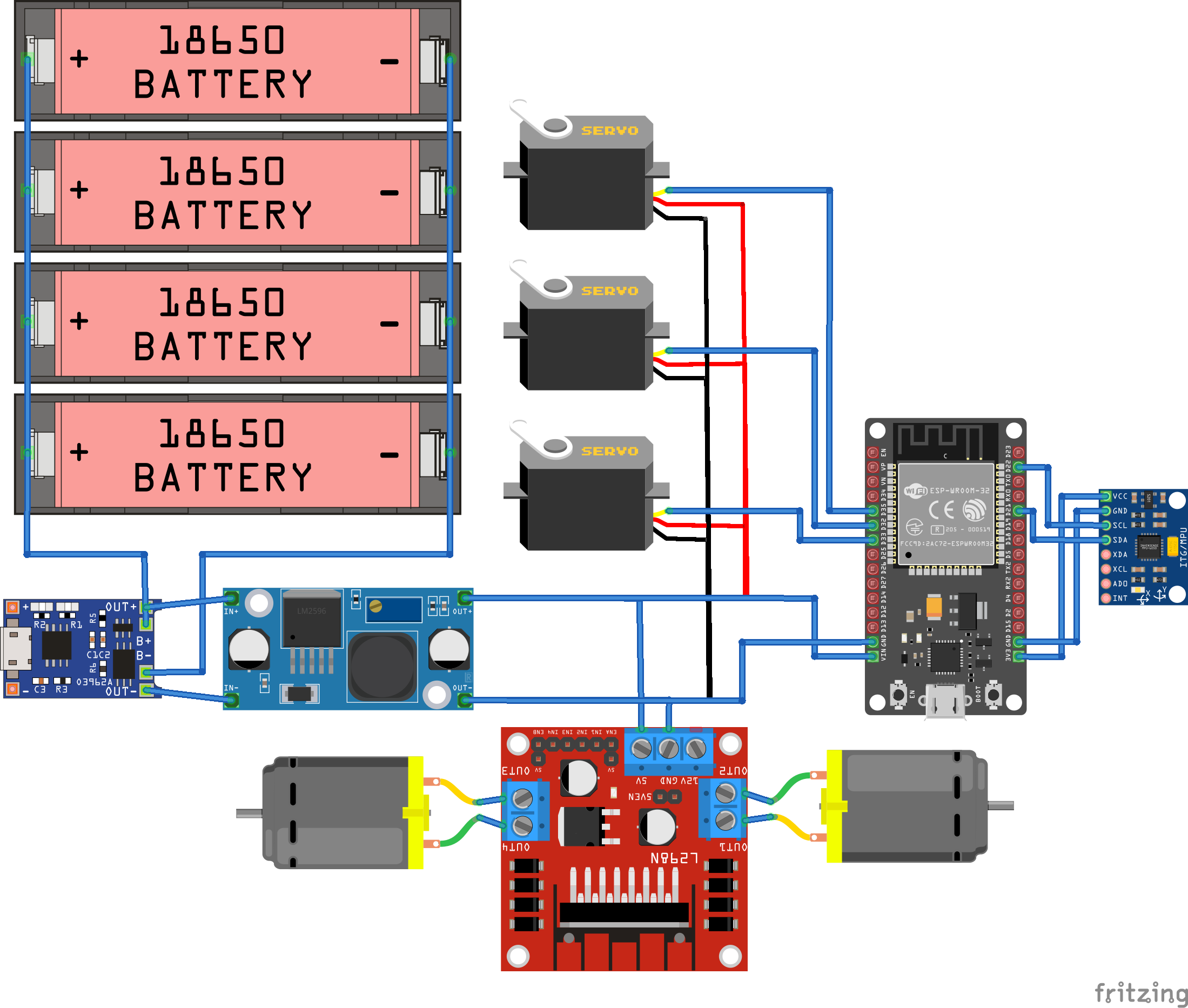
So then I had to make a board to contain all the components and give it a distribution that makes sense based on the electronics connections.
Here is the FINAL result:
Here there is a close-up view of electronics:
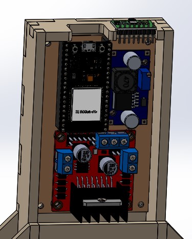
The MPU6050 was aligned to the center of the wheels axis. The TP4056 is between ESP32 and the brown board. There is an apperture at the top for connecting USB to ESP32 and to charge batteries with the TP4056.
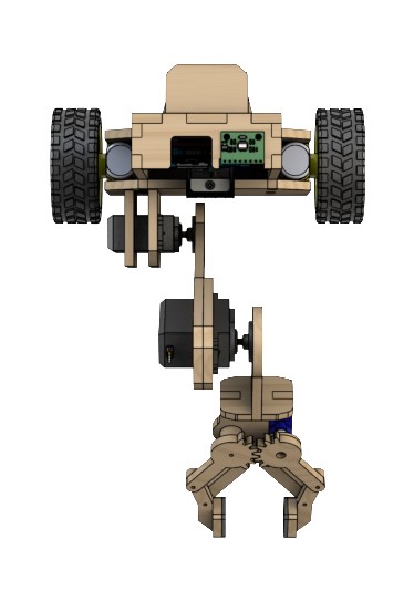
Other views:
Next step: Import into simulation enviroment
SBR (Stage 2)
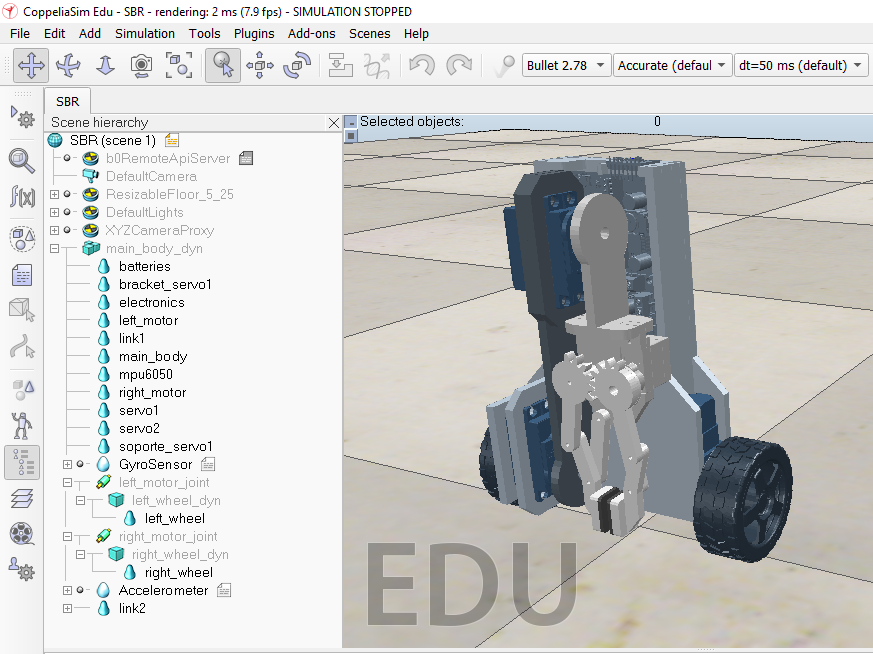
The software I chose for simulation was CoppeliaSim (V-REP), since it’s an enviroment where you can import 3D CAD files and put inertia properties, also providing sensors and signal handling. You can use an external API to connect to the enviroment (such as Matlab, Python, etc), and in my case it was Python since that’s the language I know the best.
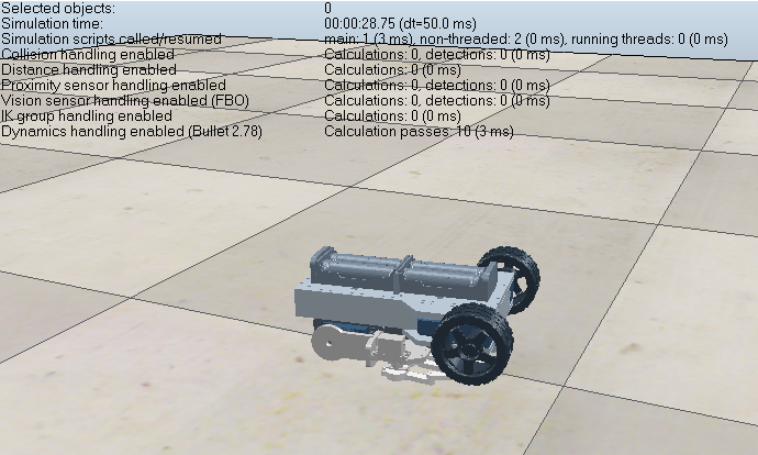
So, after importing CAD files, I had to assembly all them together again and put the calculated mass to each block. After defining the parent-child tree, it can be simulated and it should show a free fall since it has no signals driven to the motors.
Then I had to add an accelerometer and a gyroscope, since that’s what the MPU6050 is. After that, I had to connect the signals from these sensors to the external API. I recommend to use BlueZero based remote API, since it’s the newest one. After some days of searching and asking questions on CoppeliaSim forums, I had a code that works; it connects with the measurements of the sensors and also send signals to the motors to get to a desired velocity. In the background it uses a PID controller to calculate the appropiate signal to give to motors and a Kalman Filter to get an accurate tilt angle from both sensors. All this can be found on my GitHub repository.